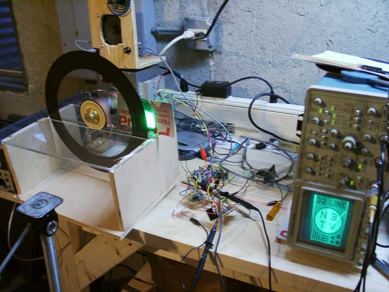
On the left is the mechanical TV chassis. Behind it on the bench is the CD player that is the source of the NBTVA
image. On the right is an alternative display: an oscilloscope that is driven by line and frame sawtooth waveforms
and the video signal from the LED driver. The tripod at left was used to photograph the image from the disc scanner.
The electronics presently runs from a fixed 12 volt supply I use for breadboarding. I intend to use a 12 volt "block"
supply that will plug into the mains (like the one that can be seen on the outlet strip in the background), and
then wire 12 volts to the chassis. The motor is a DC servo motor marked 44 volts. It requires about 17 volts DC
to reach the required 750 r.p.m. I intend to use another block supply of 30 volts and pulse-width modulate it for
servo control. At upper left on a crude chassis is the speaker and audio amp that will be built into the chassis.
This chassis also has a small battery-powered fan motor that I used to experiment with a hastily made cardboard
scanning disc.
On the new chassis, you can see the motor, disc, and makeshift shroud for the LED array. The final version of the shroud needs to be much closer to the disc and properly shielded to the dimensions of the image.
![]() Back to Mechanical TV Progress
Back to Mechanical TV Progress